Spindle bearing models refer to specific series and types of bearings designed for use in high-speed and high-precision applications, such as in machine tool spindles. These bearings come from various manufacturers and are categorized based on their design, load capacity, speed capability, and precision.
Spindle bearing models
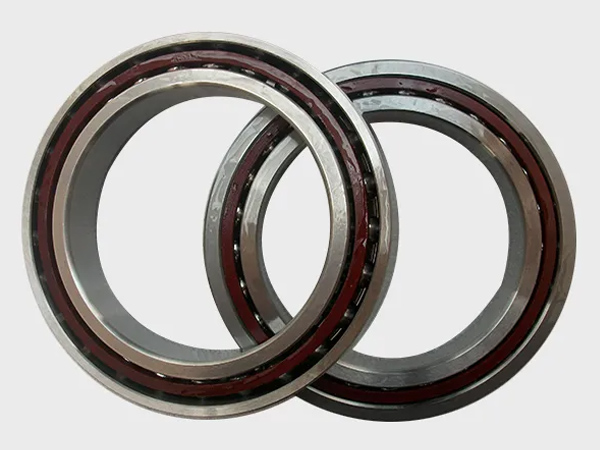
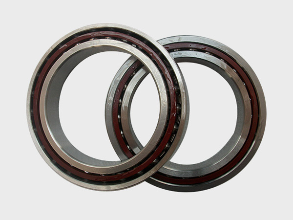
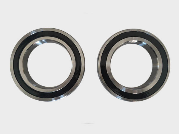
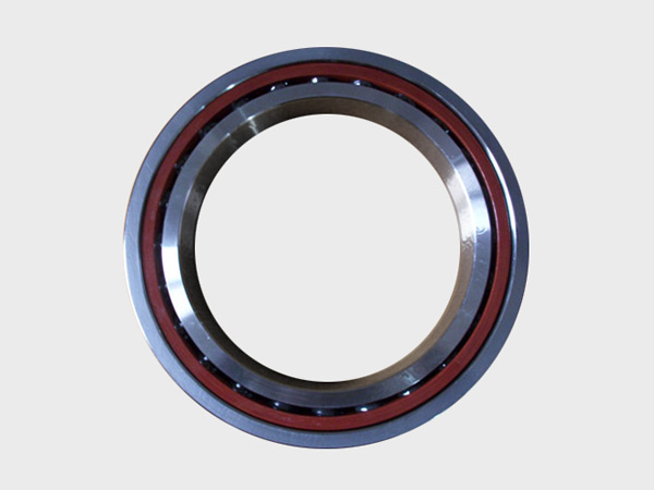
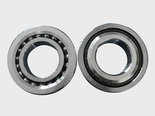
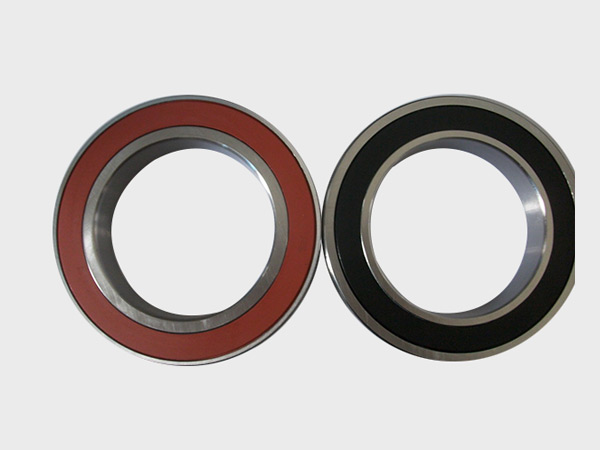
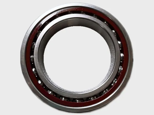
1. Angular Contact Ball Bearings
SKF 70xx, 72xx, 73xx Series:
Description: High-speed, high-precision bearings designed for applications requiring both radial and axial load capacity.
Applications: CNC machines, grinding spindles, milling machines.
NSK 70xx, 72xx, 73xx Series:
Description: Known for high precision and durability, these bearings offer various preload options to increase rigidity.
Applications: Machine tools, high-speed spindles.
FAG B70, B719 Series:
Description: Ultra-precision angular contact ball bearings with high rigidity, often used in high-speed applications.
Applications: Precision machine tools, spindles, and robotics.
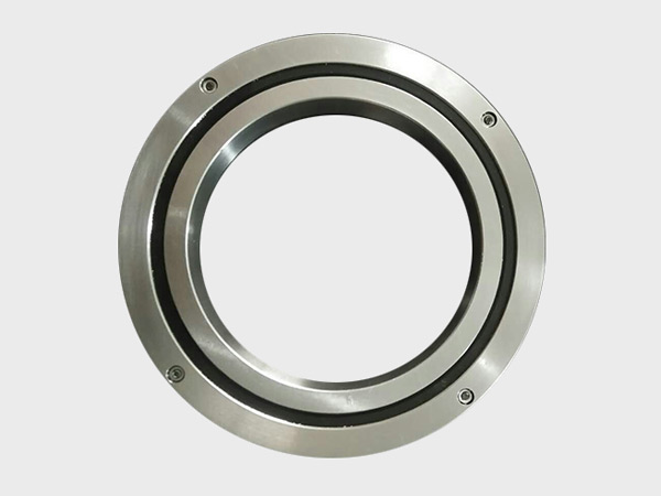
2. Cylindrical Roller Bearings
SKF N10, NUP10 Series:
Description: High-speed cylindrical roller bearings with excellent load capacity, suitable for high radial loads.
Applications: Machine tool spindles, heavy-duty machinery.
FAG N10, NUP10 Series:
Description: Designed for applications requiring high radial load capacity and high precision.
Applications: Milling machines, lathes, and other precision machinery.
NTN NN30xx Series:
Description: High-precision, double-row cylindrical roller bearings with high load capacity and rigidity.
Applications: High-precision spindles, grinding machines.
3. Tapered Roller Bearings
Timken 3xx, 4xx Series:
Description: High-load capacity bearings designed to handle both radial and axial loads in machine tools.
Applications: Spindles requiring both high load capacity and precision.
SKF 32, 33 Series:
Description: High-precision tapered roller bearings offering high stiffness and load capacity.
Applications: Lathes, milling machines, and other heavy-duty machinery.
FAG 329xx, 320xx Series:
Description: Tapered roller bearings suitable for combined load applications with high accuracy.
Applications: Heavy machinery, precision spindles.
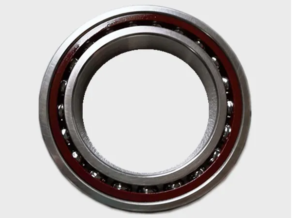
4. Hybrid Bearings (Ceramic)
SKF 719xx E B/HQ1 Series:
Description: Angular contact ball bearings with ceramic balls for high-speed and high-precision applications.
Applications: High-speed machine tools, spindles.
FAG B719xx-E-T-P4S Series:
Description: High-precision hybrid bearings with ceramic balls, offering lower friction and higher speeds.
Applications: Precision machine tool spindles.
NSK 70xxC, 72xxC Series:
Description: Hybrid angular contact ball bearings with ceramic balls for enhanced speed and precision.
Applications: High-speed spindles, aerospace, and medical equipment.
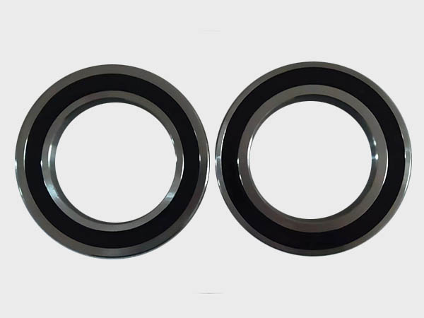
5. Thrust Bearings
SKF 2344xx Series:
Description: Precision thrust ball bearings designed to handle high axial loads in one direction.
Applications: High-precision spindles requiring axial load support.
FAG 2344xxM Series:
Description: Double-direction precision thrust bearings with high axial load capacity and rigidity.
Applications: Vertical milling machines, grinding machines.
NSK 512xx Series:
Description: Thrust ball bearings for high axial load applications with high precision.
Applications: Machine tools, precision machinery.

6. Super Precision Bearings
NSK ROBUST Series:
Description: Super precision angular contact ball bearings designed for ultra-high speeds and extreme precision.
Applications: High-speed spindles, aerospace.
SKF Super-Precision Bearings (S7014, S7214, etc.):
Description: Ultra-precision angular contact bearings offering high speeds and low vibration.
Applications: High-precision machining, optical equipment.
FAG X-life Ultra Series:
Description: High-performance bearings offering extended service life, high precision, and high speed.
Applications: Aerospace, high-speed machining.
These models represent common bearing types used in spindle applications, but there are many more variants and specific configurations available depending on the exact requirements of the machinery and the operating conditions. Always consult with a bearing specialist or manufacturer for the most appropriate model selection based on your specific needs.